Finding #1
V_bg = 16 m/s, not 25 m/s
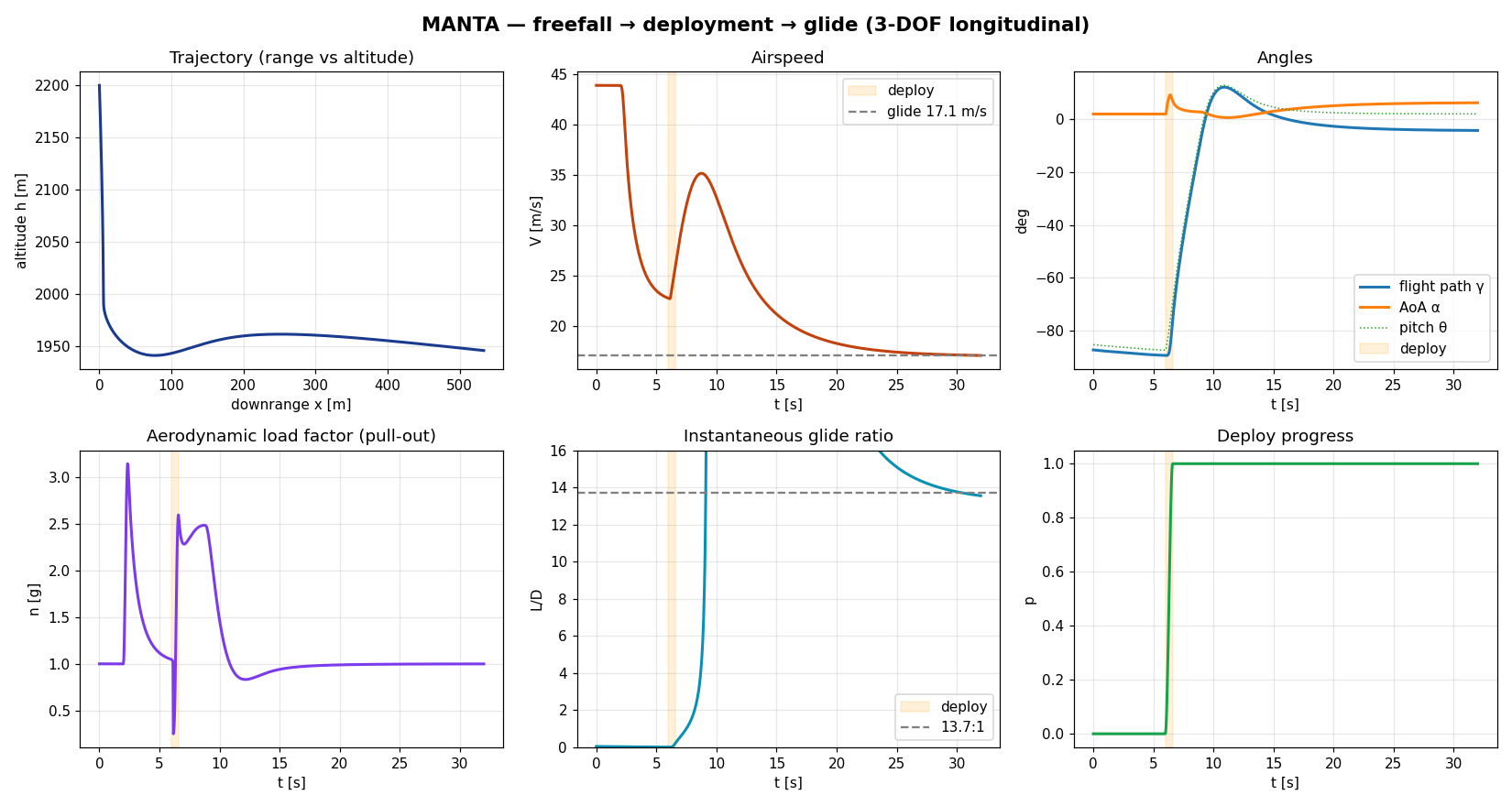
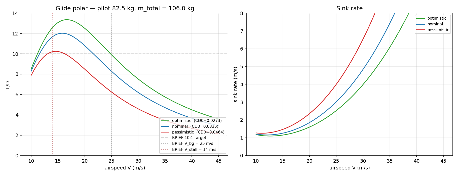
The locked planform's natural best-glide is ~16 m/s. At V = 25 m/s the wing is below its drag bucket — L/D ≈ 8.3, short of the 10:1 target.
Recommend restating BRIEF V_bg as ~16 m/s.
docs/01 →Project MANTA
Pilot wears a fitted wingsuit-derivative suit with an integrated CFRP spine yoke. The prone pilot IS the fuselage: a blended center-body fairing closes over the torso and a canopy over the head, and arm-wing membranes web the limbs into the body so the whole thing reads as one worn garment, not a human bolted to a wing. Arm-aligned rigid spars hinge from the spine as the pilot spreads; telescoping tip extensions snap out from the wrists and an ankle-rooted TE spar deploys from the body. The wing's chordwise shape is set by nine bistable rolled-composite ribs per side that unroll from coils at the spar and self-latch onto the airfoil — sprung structure, not telescoping struts. Wingsuit muscle-memory, hang-glider-class glide. Deployable rapidly in flight or on the ground.
This is a real flight vehicle program. Treat it as such.
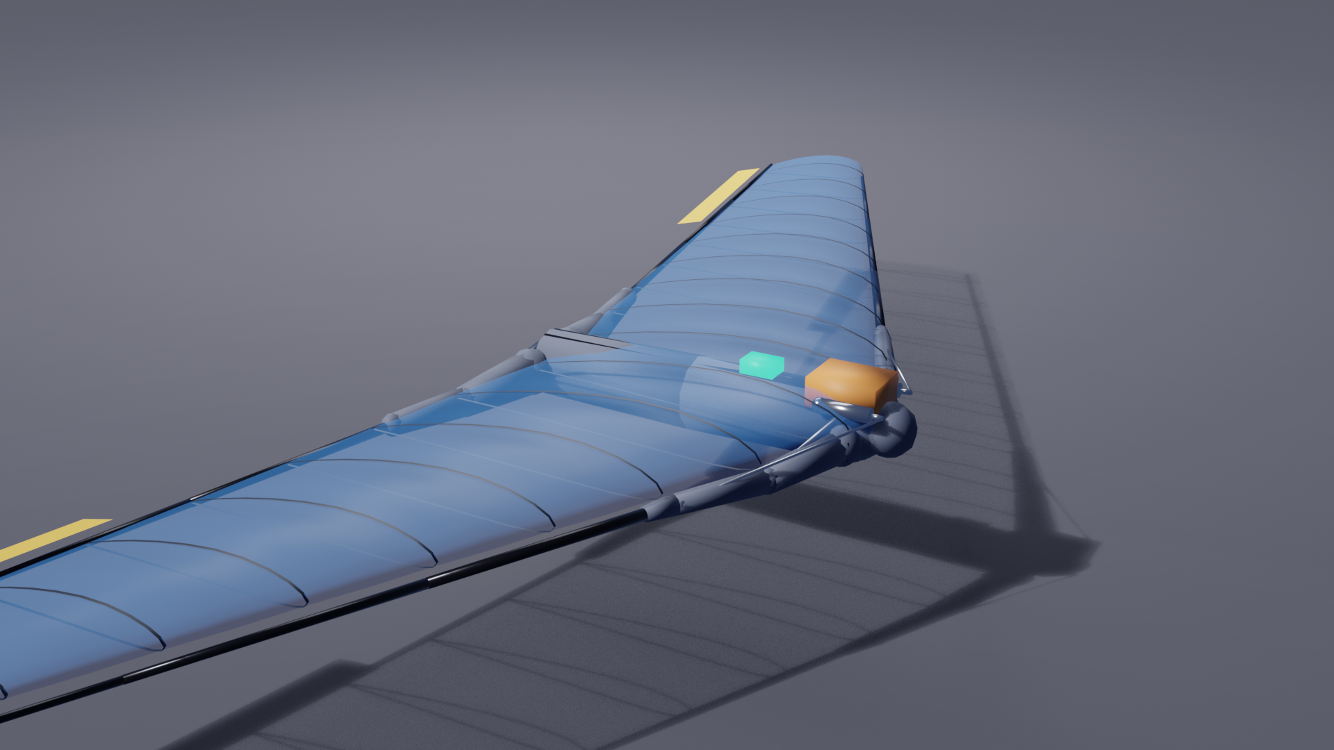
Live deployment
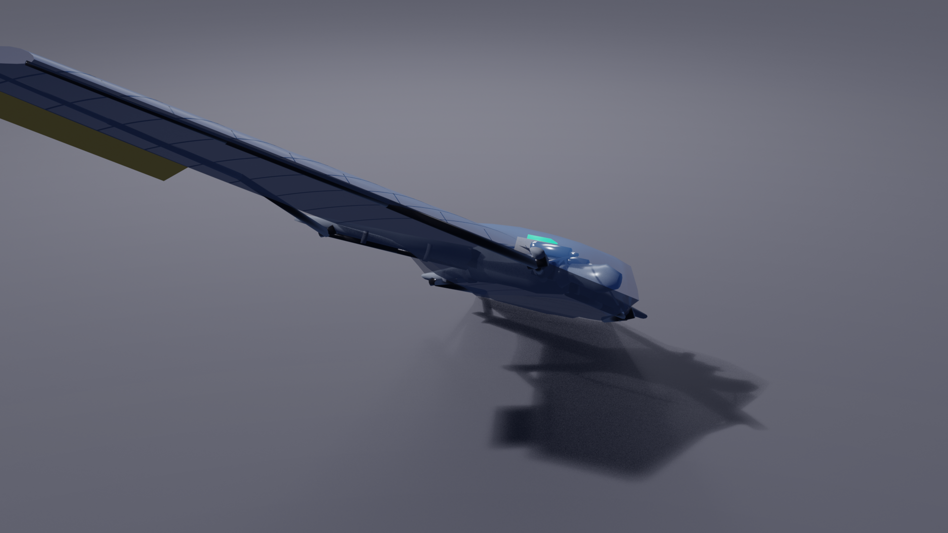
Drag to orbit. Scrub the slider through the deployment, or hit Play (Phase A: fixed-length limbs rotate out; Phase B: CO₂ telescopes the booms to full span; Phase C: nine bistable ribs per side unroll from their coils root→tip and snap onto the airfoil; Phase D: the skin tensions bay-by-bay behind the unfurl front). Then hit ‘Fly it’ and steer with the keyboard — ← → roll, ↑ ↓ pitch — to actually fly it over procedural terrain under a sky. A real reduced-order flight model runs in your browser: the equations of motion integrate airspeed, bank, load factor and angle-of-attack live, the flaperons deflect and the pilot weight-shifts as you input, the craft banks into turns and glides down toward the hills, and the α-limiter clamps the AoA so you can't stall it. ‘Flow field’ shows the surface pressure + streamlines.
Baked by sim/build.py: a deployment morph plus four control-basis morph targets (roll L/R, pitch up/down) the viewer blends from your live input. Each rib is a real coil→airfoil unroll whose easing is the integrated strain-energy ODE from analysis/deployment/rib_deploy_rom.py — the animation is physics-driven, not an ad-hoc curve. The flight model in control.json uses the resized-planform aero and the documented stability/control derivatives (analysis/flightdynamics/, docs/04) — point-mass EOM with bank-to-turn + short-period AoA + the alpha-limiter. The pilot is a fixed-proportion human inside a double-surface airfoil; the spars run inside the fabric.
Headline numbers
Wing planform is independent of mounting; the aero analyses still hold. Mass, structural, and packaging numbers updated for the corrected architecture.
Wing area
6.5 m²
Resized down from 8.4 m² — lands under reserve, so a low stall speed isn't required.
Span
6.3 m
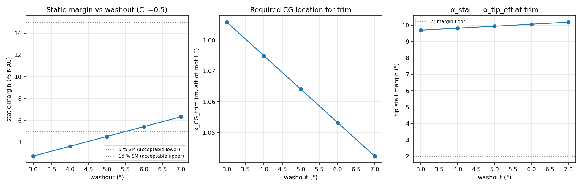
Aspect ratio 6.11, taper 0.4, sweep 25°, washout 7° (raised from 6° to recover trim margin).
CL_α (3D, Weissinger)
4.17 /rad
≈ 0.073 /deg. Helmbold cross-checked.
Static margin
5.6 % MAC
Trim study at 7° washout. But the binding CG-based margin is ~2.7% (washout-independent) — tight, FCS-managed. Alpha-limiter + yaw damper now mandatory.
(L/D)ₘₐₓ
11.6
At V ≈ 18 m/s, nominal body CdA = 0.20 m².
Dutch-roll damping ζ
0.17
At V_bg, resized planform (was 0.29). Level 2/3 — the artificial yaw damper is now mandatory, not just recommended.
Deployment time
≈ 0.6 s
Phase A arm spread + Phase B boom telescope + Phase C bistable rib unroll (≈0.69 s/rib, soft 1.96 m/s latch — rib_deploy_rom.py) + Phase D skin tension.
LE spar root OD
67 mm
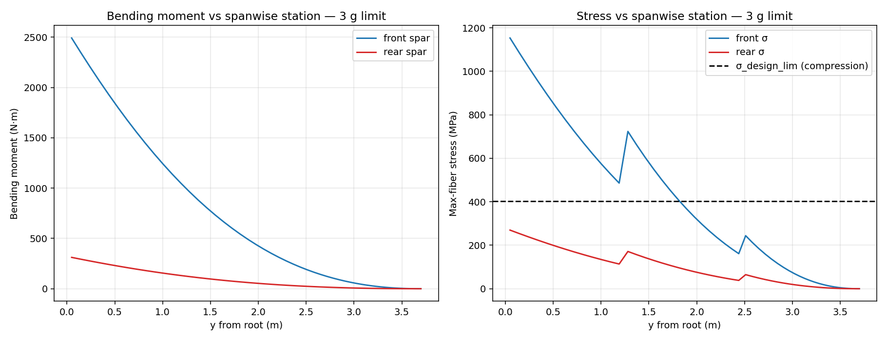
Bending-sized for the resized wing (3 g limit, SF≥1.5). Smaller than the old 73 mm — shorter span → less root moment.
Wrist tip extension
2.40 m
3-stage telescoping CFRP; CO₂-driven. Shorter boom after the resize.
Rib coil strain ε = t/2R
0.64 %
9 bistable rolled-composite ribs/side, 0.14 mm thin-ply HSC carbon wound to an 11 mm coil — within the ~1% allowable. Strain-energy drive 195 mN; rate-controlled hub prevents blossoming (passive friction holds only 0.13×).
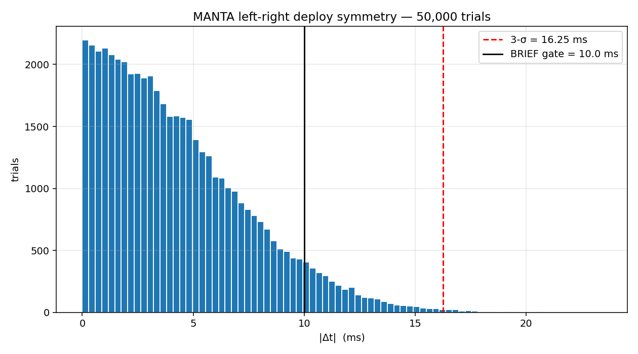
Symmetry 3-σ |Δt|
16.3 ms
vs. BRIEF 10 ms gate — locked architecture FAILS. Active modulation closes it at 8.1 ms.
Pilot 50 mm CG shift
3.6 % MAC
≈ 75% of the static margin on the smaller wing (MAC shrank to 1.095 m). ~3 cm aft and the wing goes neutral — alpha limiter mandatory.
Tests
27 / 27
Across analysis/ and fcs/. make test reproduces locally.
What the analysis surfaced
The analyses across deliverables #1–#6 plus the architecture rebuild produced four findings the BRIEF should be amended to reflect. Each is backed by runnable code; clicking through goes to the doc that defends it.
Finding #1
The locked planform's natural best-glide is ~16 m/s. At V = 25 m/s the wing is below its drag bucket — L/D ≈ 8.3, short of the 10:1 target.
Recommend restating BRIEF V_bg as ~16 m/s.
docs/01 →Finding #2
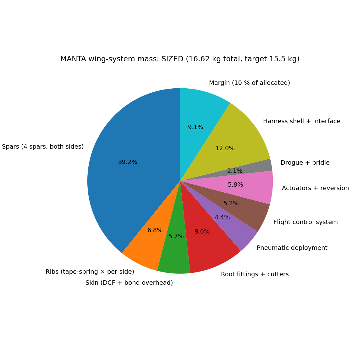
BRIEF dimensions fail bending at 3 g limit by ~3× in stress. Sized at 73 mm OD root / 2.5 mm wall. Adds +1.1 kg/side.
Now relevant to the LE spar root cross-section.
docs/02 →Finding #3
The locked passive-pneumatic-sequencing architecture cannot close the 10 ms 3-σ symmetry gate. Active modulation drops 3-σ from 16.3 ms to 8.1 ms.
Replace passive sequencing with closed-loop sensing.
docs/03 →Finding #4 — fundamental
BRIEF v1 described a separate aircraft strapped on top of a piggyback rig with pyrotechnic spar-root cutters. The actual concept is the pilot wearing a wingsuit-derivative with an arm-braced extending wing — pilot is the fuselage, structure runs along the limbs.
BRIEF v2 (current) reflects this.
BRIEF →Deliverable #1
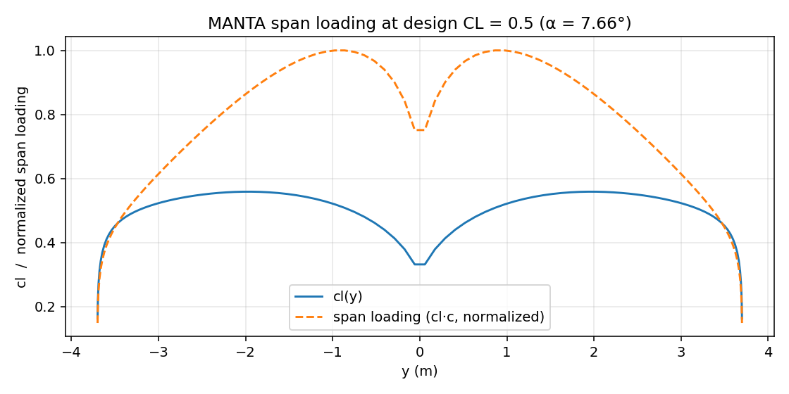
Pure-Python lifting-line, validated against Helmbold (rectangular AR=8: −3.4 %), feeds trim, glide polar, and the parametric wing OML. Wing planform is independent of how it integrates with the pilot — these numbers carry over from BRIEF v1 unchanged.
Deliverables #2 + #3
Bending analysis uses Weissinger output as the loading shape. The cantilever load path in the new architecture is from wingtip → telescoping booms → wrist hub → along-arm LE spar → shoulder yoke → spine. Bending magnitudes carry over; the path is shorter and the moment is reacted by the spine yoke rather than a sub-frame.
Deliverables #4 + #5
The wing's chordwise shape is set by nine bistable rolled-composite ribs per side that unroll from coils at the spar (Phase C) — a strain-energy ROM gives the snap time and soft-latch velocity, and a membrane form-finding model shows the deployment tensions the skin into a smooth controlled surface (0.27% waviness, well inside aero tolerance). The state machine implements every gate and abort path; a 50,000-trial Monte Carlo characterizes the symmetry budget, where the CO₂ contributor busts the 10 ms 3-σ BRIEF gate alone.
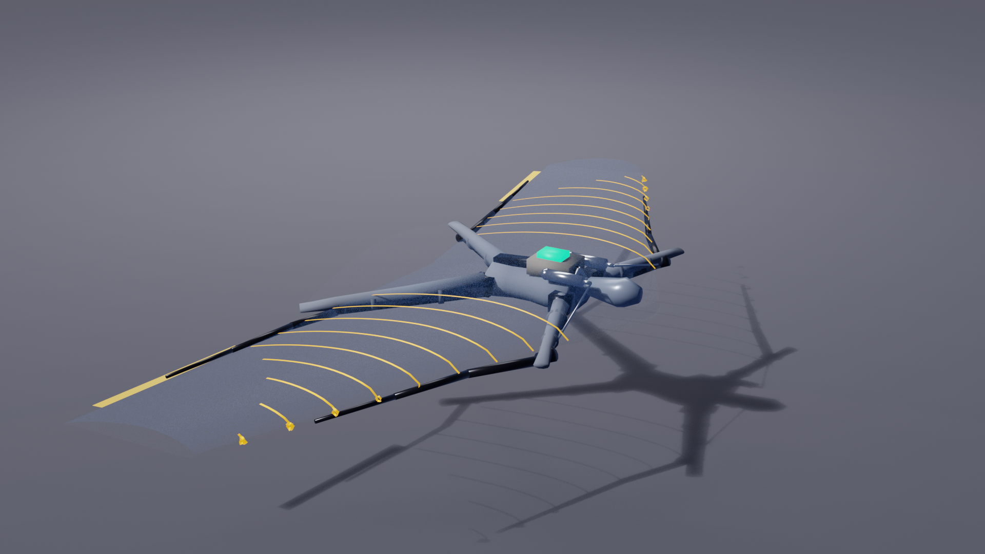
sim/build.py: rib_unroll).
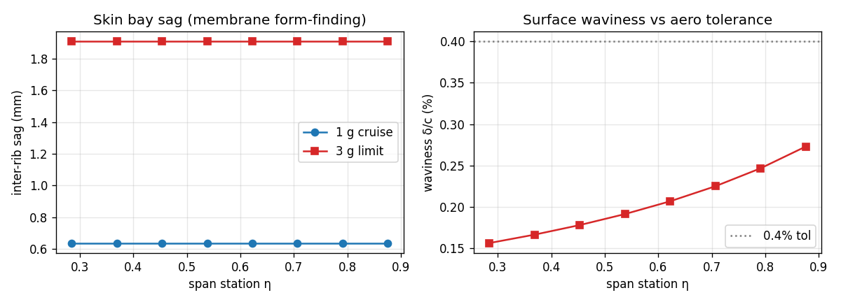
analysis/deployment/membrane_formfinding.py): the deployment pretensions the skin (~2.2 kN/m), so the worst inter-rib sag is ≈1.9 mm even at 3 g — a surface waviness of 0.16–0.27% chord, inside the 0.4% aero tolerance. The deployed wing is a smooth controlled surface, not a billowing canopy; the model now renders this physical sag (≈1.5% of thickness), not an arbitrary bulge.
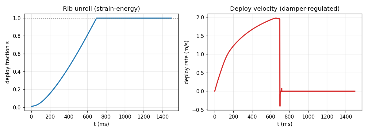
analysis/deployment/rib_deploy_rom.py): each rib snaps coil→latched airfoil in ≈0.69 s under a constant 195 mN Seffen–Pellegrino propagation force; the damped hub bleeds the stroke to a soft 1.96 m/s latch and prevents blossoming (passive friction holds only 0.13× the drive).
FCS architecture
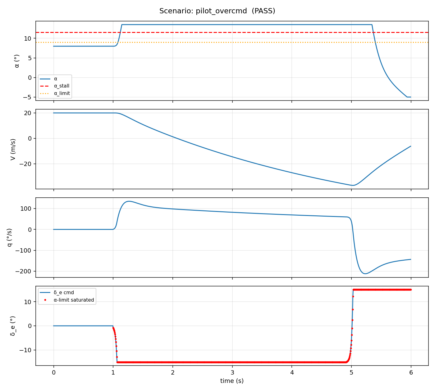
Per BRIEF, the alpha limiter is treated as an invariant the structure depends on. Pilot CG perturbations alone can eat the static margin; without active envelope protection, a 50 mm posture shift can destabilize the wing. The shoulder/hip rotation against the locked spar gives the pilot a wingsuit-style direct control path that maps to alpha command.
Where each deliverable stands
Every BRIEF first-deliverable closed end-to-end with runnable analysis, real CAD, tests where logic exists, and an explicit open-issues section where the analysis stopped.
| BRIEF | Deliverable | Doc | Tests | Status |
|---|---|---|---|---|
| #1 | Aero sizing | docs/01-aero-sizing.md | 5 ✓ | first-cut |
| #2 | Mass budget | docs/02-structural-budget.md | 8 ✓ | first-cut |
| #3 | Spar bending | docs/02-structural-budget.md | 8 ✓ | first-cut |
| #4 | Deployment sequence | docs/03-deployment-sequence.md | 7 ✓ | first-cut |
| #5 | Symmetry budget | analysis/deployment/symmetry-budget.md | — | first-cut — fails 10 ms gate |
| #6 | Ground rig spec | test/ground/spec.md | — | spec drafted |
| + | FCS architecture + alpha limiter | docs/04-fcs-architecture.md | 7 ✓ | first-cut |
| + | Emergency systems | docs/05-emergency-systems.md | — | first-cut |
| + | Test plan | docs/06-test-plan.md | — | first-cut |
| + | Pilot training transition | docs/07-pilot-training.md | — | syllabus drafted |
| + | Lateral-directional dynamics | analysis/flightdynamics/lateral.py | — | first-cut |
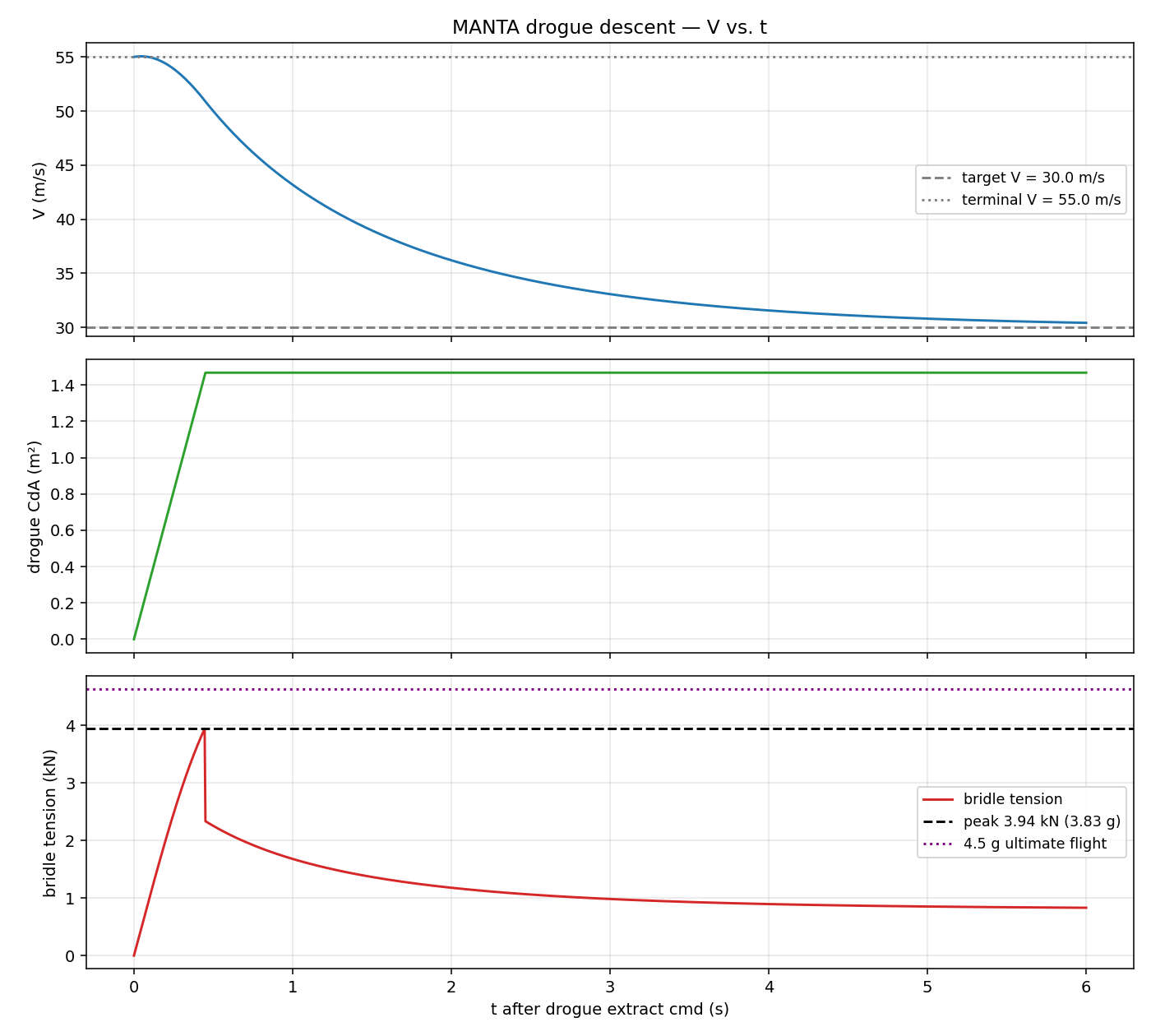
| + | Drogue dynamics | analysis/deployment/drogue_dynamics.py | — | first-cut |
| + | FMEA — 11 / 14 per-mode files | safety/fmea.md | — | first-cut |
| + | Bench characterization plan | test/bench/README.md | — | spec drafted |
27 / 27 tests passing across analysis/ and fcs/.
Engineering culture
This project kills people if done sloppily.
Every analysis is reviewable. Every assumption is cited. Every safety-critical claim has a test that backs it. No vibes-based engineering.
Would this analysis hold up if a coroner's office asked for it?